STEP 3: Software Setup
3.1 Introduction to the Machine's Auto Focus, Z-Axis Reset, Z-Axis Lowering by 2mm, and Red Crosshair Offset Features
1.Connect the laser engraver to a computer with USB cable.
2.Plug in the power adapter of the laser engraving machine.
3.1“Auto focus” ,“Z-axis reset”and“Z Down 2mm” “Red cross.”
3.1.1 GM1 has autofocus function:Unlike the traditional manual focus mode, gluwphy aim has an autofocus function, which is more accurate and more convenient, you can set up the autofocus part according to our introduction below.
3.1.2 Z-axis reset and Z Down 2mm:(When cutting thick boards, laser's light waist can't be satisfied, which will lead to poor cutting results, at this time, sinking the laser, which helps to improve the cutting effect)Users only need to add buttons in the corresponding engraving software, The setting method is as described in part 4.(instruction manual)
Users can also log in to: https://support.gluwphy.com to view course.
3.1.3 Red cross offset:The GM1 has the Red Cross positioning function, but due to the different positions of the Red Cross and the laser light output there will be an offset, you can set the offset in the following way, you can also find the setting method in part4 chapter 5 section(instruction manual)
3.2 Set Auto Focus, Reset Z-Axis, Lower Z-Axis by 2mm, and Red Crosshair Offset in LightBurn Software
3.2 Lightburn Basic setup and software usage
Basic settings in lightburn
3.2 How to Set "Autofocus", “Z-axis reset”, “Z Down 2mm” “Red Cross Offset to Laser” in Lightburn
3.2.1 How to use "Autofocus" function :
- Turn on the "Autofocus" function.
- Select the engraving file, the machine will automatically start focusing after clicking Start, and start engraving after the focus is completed.


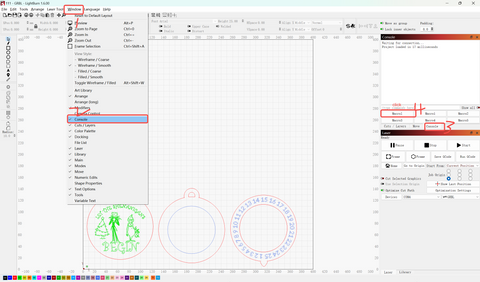
- Select any custom button, right click mouse to pop up the button setting page, enter the name of the button in "Button Label", enter [$HZ] under "Macro contents"
- After clicking OK, a button with the corresponding function will be generated

3.2.2, How to raise the Z-axis to the highest - Z-axis reset
- When you need to engrave or cut a thicker object, you need to raise the z-axis to put the object in, and then you can reset the z-axis.
- Find "Window" in the top navigation bar, and enable "Console" function in the drop-down menu, Just like the steps for autofocus.
- Select any custom button, right click mouse to pop up the button setting page, enter the name of the button in "Button Label", enter [$J=G91 Z100 F200] under "Macro contents

- After clicking OK, a button with the corresponding function will be generated.
3.2.3 How to drop the laser head 2mm
- When you cut thick objects, you can drop the laser head by 2mm, making the focal length drop by 2mm for a perfect cut!
- The steps are the same as before.
- Select any custom button, right click mouse to pop up the button setting page, enter the name of the button in "Button Label", enter [$J=G91 Z-2 F200] under "Macro contents" .


3.2.4 How to set Red Cross Offset to Laser in Lightburn
1, Launch Lightburn and Connect to the device.
2, Go to edit-> Device Settings -> Laser Offset -> Enable Pointer Offset.
3, For GM105 and GM120, fill in -12mm at X and -12mm at Y;For GM110, fill in -12mm at X and - 10.6mm at Y

3.2.2 Introduction to LightBurn Software Interface - Engraving and Cutting
3.2.2 Introduction to the use of lightburn software
3.2.2.1 Lightburn interface Introduction
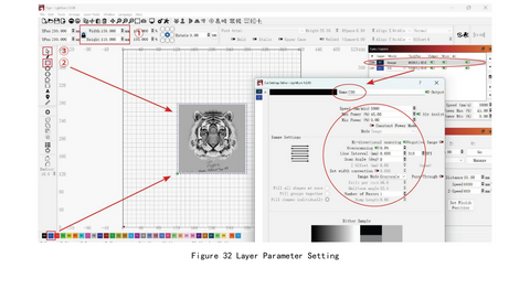
Import Image: Click the Open button, select supported format, select and import an image

Size adjustment: Adjust the image size in ① . When in the locked state, adjust either the Width or Height number, and the other number will change synchronously compared to the same column.
Drawing:Use the square drawing tool in ② to draw a square, adjust the size of the drawing in ① .
Create layer: In ③ , select the drawn square, click on the blue bottom left corner to create layer C01.
Layer parameter setting: Click on layer C00 to enter the parameter setting interface, and refer to the attached parameter table to set .


3.3 LaserGRBL Basic Setup and Software Usage
3.3 Basic settings in LaserGRBL:
3.3.1 How to Set "Autofocus", “Z-axis reset”, “Z Down 2mm” “Red Cross Offset to Laser” in LaserGRBL:
- We have packaged LaserGRBL's function buttons so that you can import the buttons at once.
- You need to go to support.gluwphy.com to download the button file
"Gluwphy_GM_GRBL_Button.zbn" first.
https://cdn.shopify.com/s/files/1/0853/5674/0892/files/Gluwphy_GM_GRBL_Button.zbn?v=1717577276
- At the bottom of the laserGRBL interface, click the right button of your mouse and choose”Impot custom buttons”, as follows:


- Follow the prompts and select Yes for all.
- As shown below, the newly added button, 01 is the "Autofocus",02 is the “Z-axis reset”,03 is the“Z Down 2mm”

3.3.2 How to set Red Cross Offset to Laser in LaserGRBL
1, Launch LaserGRBL and Connect to the device.
2, Import the image to be processed, and the Target image dialogue box appears, and click next.
3, Find offset in the target dialog box, For GM105 and GM120, fill in -12mm at X and -12mm at Y;For GM110, fill in -12mm at X and -10.6mm at Y

3.3.2 LaserGRBL Software Setup
3.3.2 Introduction to the use of LaserGRBL software
3.3.2.1 Operating instructions
1.Connect the laser engraver to a computer with USB cable.
2.Plug in the power adapter of the laser engraving machine.
3.Open LaserGRBL.
4.Install CH340 Driver. In LaserGRBL , click < Tools > < install CH340 Driver > to install the driver, and restart the computer after installation

COM ports can be viewed in your computer's Device Manager

Select the correct port number and baud in the software - 115200 (In general, COM ports do not need to be selected manually, but if you have more than one serial device connected to the computer, it needs to do so, you can find the port of the laser engraving machine in the device manager of the windows system, or you can simply try the port numbers displayed one by one).

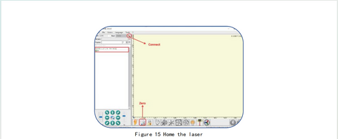
Click on the lightning connection button in the software. When the lightning button turns red,the connection is success. 0n the bottom-right of the LaserGRBL interface you should read "status:Idle".

If you see “ Disconnected” or “Connecting” but no message come from the engraver, you should change COM port.If you see “Status: Alarm" it means that your board is in an alarm state. The machine is connected.

Usually when the machine is in Alarm status it is necessary to execute the homing procedure(Click the HOME button)or simply press the Unlock button to acknowledge the alarm (or enter“ $X" in the command box).

3.3.2.2 Instructions of buttons

3.3.2.3 Parameter settings:Engraving and cutting

3.3.2.3.1 Engraving parameter settings

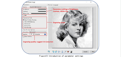
- a) LaserGRBL can adjust the brightness, contrast, white clip and other attributes of the target image.
When adjusting the parameters of the image, the factual effect will be shown in the right preview window, and adjust it to your satisfaction.
-
b)It usually chooses "Line To Line Tracking" and "1bit BW Dithering" as engraving mode. "1bit BW Dithering" is more suitable for engraving grayscale images; If you are going to cut, please select the "Vectorize" or "Centerline" mode so it will cut along thin line.The red trace in the preview box represents the laser engraving path.
-
c) Engraving quality essentially refers to the line width of laser scanning, this parameter mainly depends on the size of the laser spot of the laser engraving machine. our laser engraving machine uses rectangular compressed spot of 0.08·0.08mm, so it is recommended to use the engraving quality range of 8-10 lines/mm. Different materials respond differently to the laser, so the exact value depends on the specific engraving material.
4.
d) At the bottom of the preview window, the image can also be rotated, mirrored, cut, etc.Engraving speed, power and size setting
a)Choose different speeds and engraving power according to the hardness of different materials. We have attached engraving and cutting parameters of common materials in the manual for your reference.
b)There are two laser modes in the laser options, M3 and M4. M3-Constant power mode simply keeps the laser power as programmed, regardless if the machine is moving, accelerating, or stopped. This can lead to more consistent cuts in more difficult materials. M4-Dynamic power mode will automatically adjust laser power based on the current speed relative to the programmed rate. It essentially ensures the amount of laser energy along a cut is consistent even though the machine may be stopped oractively accelerating.
Note: If your M4 laser mode is not available, please check your GRBL configuration to make $32=1.
- c) Set a suitable size according to the size of your engraving material.
- d) Finally, click on the <create> button to complete the setting of all engraving parameters.

3.3.2.4 Positioning
Home laser. Click the HOME button, the laser will move forward to the front left. After homing,the default engraving origin is from the front left, and the engraving object needs to be placed along the origin.
Note: If the laser is not homed, t may cause the laser to exceed the working area.

Click the <Frame> button, the laser will start to scan the outer frame of the image.You can adjust the position of the engraving object according to the scanned frame area.

Tips for accurately positioning images and engraving objects
- a) Move the laser to the let front of the frame.
- b) Use a ruler and pencil to draw a center point on the engraved object.
- c) Click on the following two buttons one after the other to move the laser so that the laser point moves to the center of the engraving, which will makes a more accurate positioning.

3.3.2.5 Start and stop engraving/cutting
Start engraving/cutting
After completing all the above settings, click the green button as shown in the Figure 18 to start
engraving/cutting. There is an editable number next to the start button, and this number is the
times of engraving /cutting. LaserGRBL allows multiple consecutive operations on the same image.
This function is especially useful for cutting
Stop engraving/cutting
If you want to stop engraving/cutting while the machine is running, you can click the stop button as shown in the Figure 19 to stop engraving/cutting.
Feed hold and resume
If you just want to pause while the laser is running and will resume unfinished work, you can click the feed hold and resume button as shown in Figure 20

You can also follow the video below to learn the use of lasergrbl
https://gluwphy.com/pages/video-of-software


